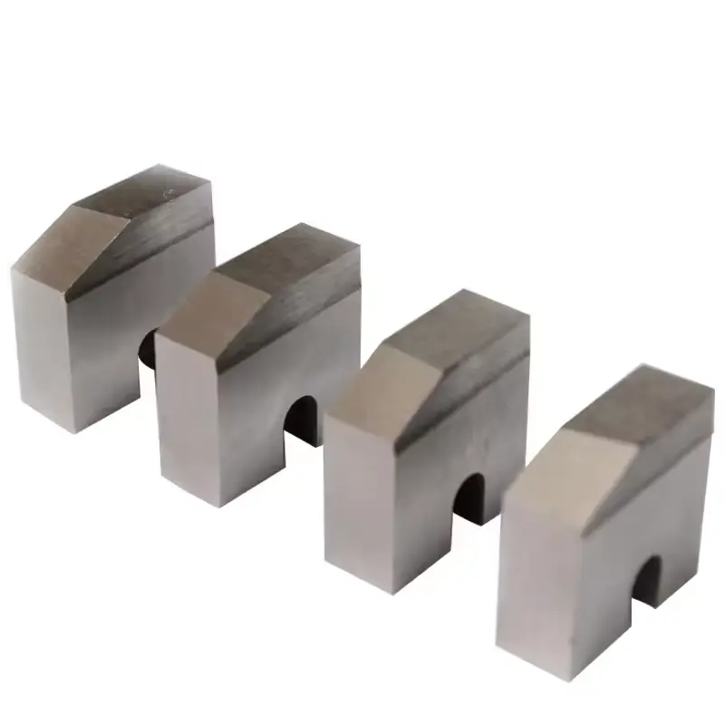
Rib peeling blade for rebar thread rolling machine
Description
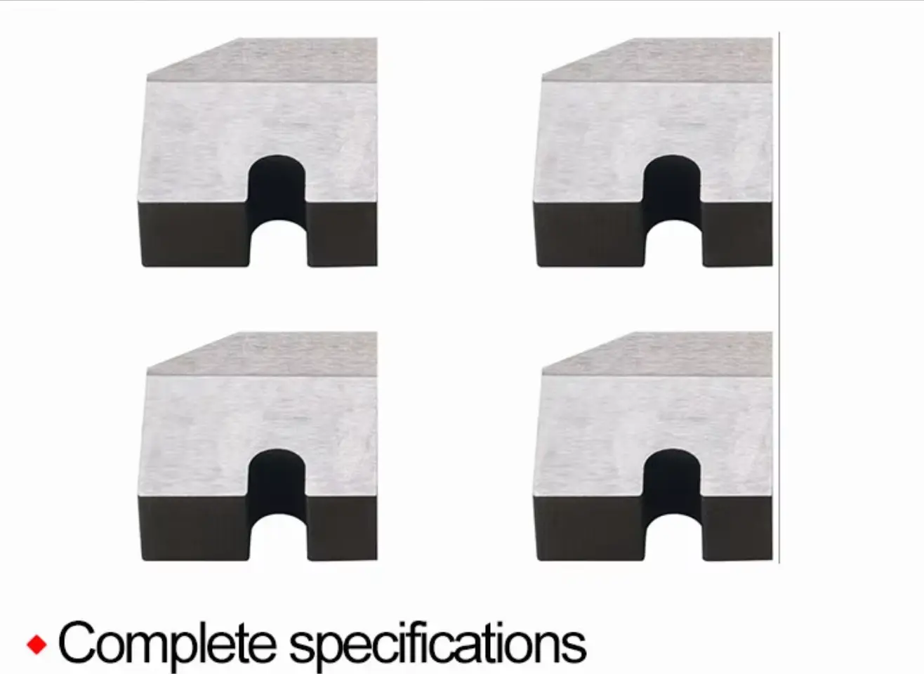
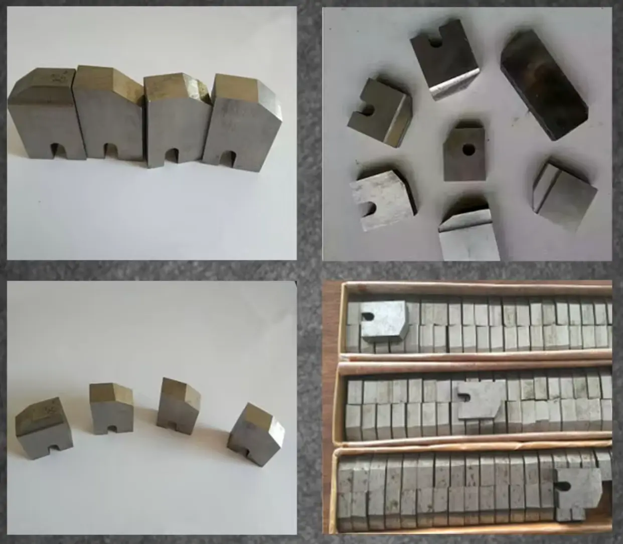
This set of rib peeling blade for rebar thread rolling machine, efficiently removing thread ridges from steel bars ranging from Φ16 to Φ40 in diameter. The kit comprises four pieces, each conforming to standard specifications with uniform parameters for outer diameter, length, inner diameter, and pitch. Suitable for diverse construction projects and manufacturing plant applications, these tools deliver precise performance and robust durability.
rib peeling blade Attribute and Specifications
| Product Details | |
| Product Name | Rib Peeling Blade |
| Brand Name | Anda Machinery |
| Marketing Type | New Product 2020 |
| Condition | New |
| Place of Origin | Hebei, China |
| Rebar Diameter | 16-40mm |
| Fit For | Deformed Bar (Rebar) |
| Specifications | |
| Power | 5.5 W |
| Voltage | 380 V |
| Dimension (L*W*H) | 25*25*30 cm |
| Weight | 0.2 kg |
| Single Gross Weight | 2.000 kg |
| Color | White |
| Sales & Service | |
| Selling Units | Single item |
| Production Capacity | 100 units/day |
| Warranty of Core Components | 1 Year |
| After-sales Service | Online Support |
| Showroom Location | Canada, Spain |
| Key Selling Point | Energy Saving |
| Certification & Docs | |
| Certification | CE |
| Machinery Test Report | Provided |
| Video Outgoing-inspection | Provided |
| Core Components | PLC, Motor |
rib peeling blade descriptions
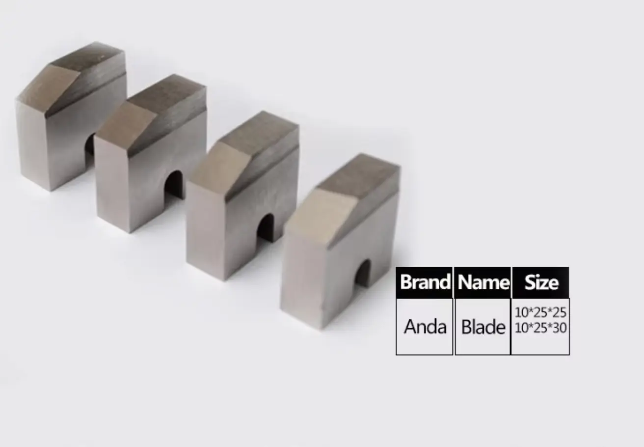
It is installed in the machine head of rebar thread rolling machine, and used to peel ribs of rebar. 4 pcs/set.
| Dia. of Rebar | Φ16- Φ22 | Φ25- Φ32 | Φ36- Φ40 |
| Outer Dia | 78.3 mm | 70 mm | 60 mm |
| Length | 45 mm | 45 mm | 45 mm |
| Inner Diameter | 30 mm | 30 mm | 30 mm |
| Thread Pitch | 2.5 mm | 3 mm | 3 mm |
How to replace the rib peeling blade on a rebar thread rolling machine
1. Preparatory Work:
- Switch off the equipment and disconnect the power supply to ensure operational safety;
- Prepare suitable tools such as Allen keys, screwdrivers, etc.;
- Verify that the new blade specifications match the equipment requirements.
2. Removal of Old Blade
- Open the machine head guard and locate the fixing screws or nuts for the deburring blade;
- Use appropriate tools to loosen the fixing screws and remove the old blade. Some equipment may require prior removal of the deburring disc or related components to fully extract the blade; take care to avoid damaging other parts during this process;
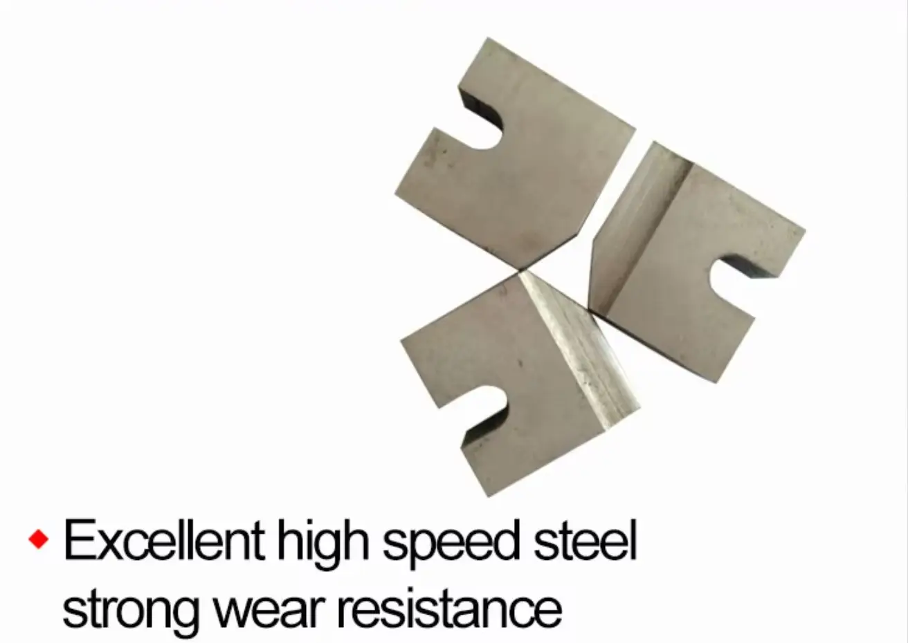
- After cutting a certain quantity of steel bars, the deburring blade’s cutting edge will become blunt. At this point, remove the blade and grind 0.2-0.3mm from the front cutting surface (strictly avoid grinding the top surface of the cutting edge). Reinstall for reuse;
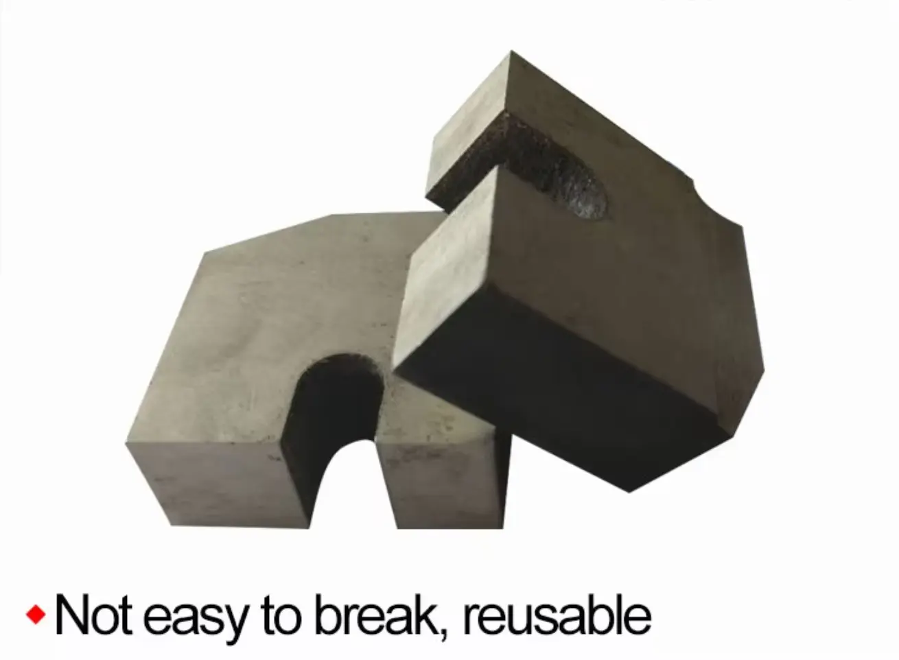
- Should the blade edge crack and fail to cut properly, replace it with a new blade.
3. Installing the New Blade
- Correctly mount the new blade onto the blade holder or disc, ensuring it sits flush with the disc surface without tilting or misalignment.
- Tighten the fixing screws to secure the blade firmly, taking care not to apply excessive force which may damage the blade or holder.
4. Adjustment and Inspection
- After installation, refit the cutting head guard;
- Before energising the power supply, manually rotate the cutting head to verify smooth blade rotation without binding or collision;
- Conduct a no-load trial run to observe normal equipment operation and adequate coolant supply;
- If the equipment features adjustable parameters such as stripping length or diameter, recalibrate these settings according to the new blade specifications to ensure machining accuracy meets requirements.