Full grout coupler for precast concrete
Description
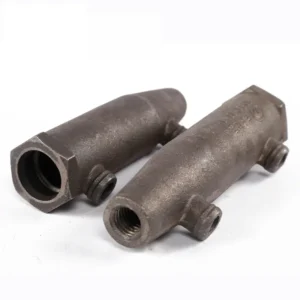
Full grout coupler, also known as grouted sleeve joints or sleeve grouting joints, constitute a meticulously engineered composite assembly. They comprise specially machined sleeves, materials specifically formulated for grouting, and reinforcing bars. During installation, the reinforcement bars are firmly bonded to the sleeve through the injection of a rapid-setting, non-shrink grout. This method leverages the adhesive and interlocking properties between the materials. This jointing technique not only delivers robust performance and broad applicability but also offers an exceptionally straightforward installation process.
Example diagram for full grout coupler for precast concrete
Advantages of Full Grout Rebar Coupler
1. Excellent Structural Performance
- Provides high tensile and compressive strength, equal to or greater than the parent rebar.
- Ensures stable mechanical connection without slippage or thread failure.
- Suitable for high-strength and large-diameter rebar such as HRB500 or HRB600.
2. Easy and Efficient Installation
- No threading or heating required — simple insertion and grouting process.
- Allows for greater construction tolerance, ideal for precast assembly on site.
- Multiple joints can be grouted simultaneously, improving construction speed.
3. High Safety and Durability
- Dense grouting offers excellent corrosion resistance and long service life.
- Performs well under seismic conditions, widely used in earthquake-resistant structures.
- Connection quality can be easily tested for grouting density and strength.
4. Wide Application in Modern Construction
- Ideal for precast concrete structures such as columns, beams, and walls.
- Extensively used in bridges, tunnels, metro systems, high-rise buildings, and nuclear projects.
- Compatible with both vertical and horizontal grouting systems.
Parameter Table for Full Grout Coupler
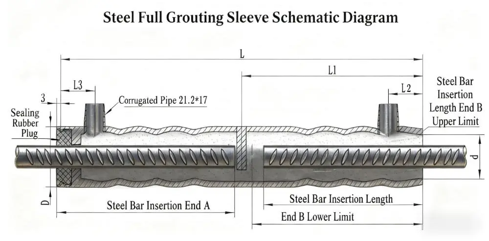
| Model | Rebar Diameter | D | L | Inner Diameter of Grout coupler (d) | L1 | L2 | L3 | Rebar Insertion at End A | Rebar Insertion at End B (Upper Limit) | Rebar Insertion at End B (Lower Limit) | Weight (KG) |
| GTJQ4 12 | Φ12 | Φ44 | 250 | 32.5 | 125 | 32 | 30 | 124 | 106 | 96 | 1.05 |
| GTJQ4 14 | Φ14 | Φ46 | 280 | 34.5 | 140 | 32 | 30 | 139 | 122 | 112 | 1.3 |
| GTJQ4 16 | Φ16 | Φ48 | 315 | 36.5 | 158 | 32 | 30 | 156 | 138 | 128 | 1.6 |
| GTJQ4 18 | Φ18 | Φ50 | 345 | 38.5 | 174 | 32 | 30 | 170 | 154 | 144 | 1.85 |
| GTJQ4 20 | Φ20 | Φ52 | 375 | 40.5 | 189 | 40 | 30 | 185 | 170 | 160 | 2.6 |
| GTJQ4 22 | Φ22 | Φ54 | 410 | 42.5 | 206 | 45 | 30 | 203 | 186 | 176 | 2.8 |
| GTJQ4 25 | Φ25 | Φ58 | 455 | 46.5 | 229 | 45 | 30 | 225 | 210 | 200 | 3.45 |
| GTJQ4 28 | Φ28 | Φ63 | 505 | 50.5 | 255 | 45 | 30 | 249 | 234 | 224 | 4.6 |
| GTJQ4 32 | Φ32 | Φ67 | 570 | 54.5 | 288 | 45 | 30 | 281 | 266 | 256 | 4.75 |
Comparison of core parameters between half grouted sleeve and full grout coupler
| Comparison Dimension | half Grouting Sleeve | Full Grout Coupler |
| Connection Method | One end uses grout connection; the other end uses threaded connection (typically straight thread). | Both ends use grout connection; no threaded structure. |
| Applicable Scenarios | 1. Rebars can be pre-threaded during prefabrication; only one end needs on-site grouting. | 1. Rebars on both ends need on-site insertion and grouting; no pre-threading required. |
| 2. Suitable for scenarios requiring fast installation or with limited on-site operating space. | 2. Suitable for scenarios where rebars cannot be rotated or both ends need flexible adjustment of insertion depth. | |
| Structural Features | Contains partial internal threaded sections; smaller grout cavity volume; relatively shorter overall length. | No internal threads; full grout cavity; relatively longer overall length; more uniform wall thickness. |
| Installation Difficulty | Moderate – requires ensuring torque for threaded connection and controlling grout quality. | Lower – only needs to ensure qualified insertion depth of rebars on both ends; focus on grout fullness. |
| Rebar Requirements | Rebars for the threaded end need pre-rolling or rib-stripping processing; high precision required. | Rebars on both ends can be plain or ribbed; no additional threading processing needed. |
| Cost Level | Relatively lower – threading adds some cost, but material consumption is less. | Relatively higher – longer length increases material consumption; larger grout volume also adds cost. |
| Mechanical Properties | Tensile strength and ductility meet code requirements; threaded section is a potential stress concentration point. | More uniform overall stress; no threaded weak points; higher stability in mechanical properties. |
How to install a full grout coupler
1. Precast Component Production Phase (Factory Fabrication)
1.1 Pre-Assembly of Sleeve Left End (Plug and Rebar Installation)
1.2 Rebar Bundling and Formwork Placement
1.3 Positioning of Sleeve Right End and Fixture Installation
1.4 Fixture Fixing and Concrete Pouring

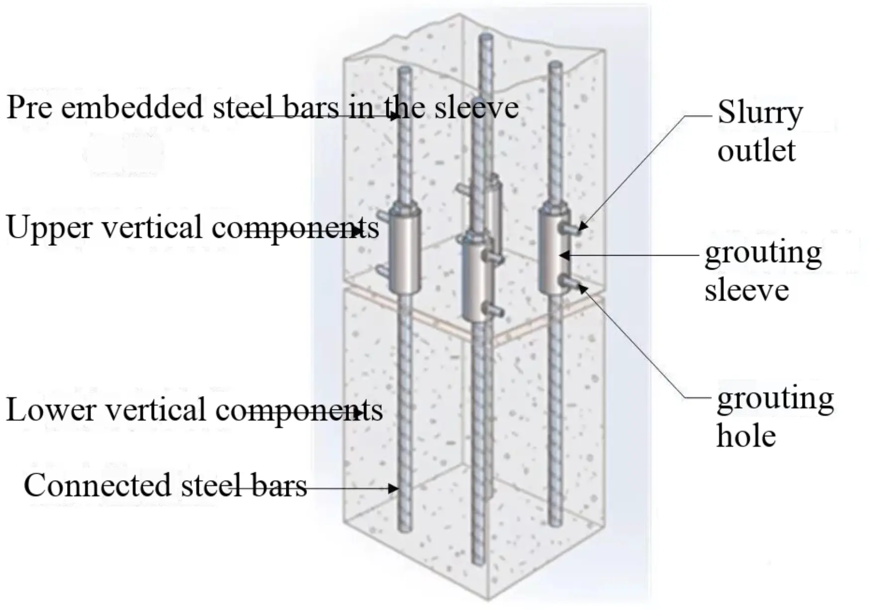
2. On-Site Installation and Connection Phase (Site Construction)
2.1 Component Alignment and Sleeve Coupling
2.2 Sealing/Grouting Bed Treatment
2.3 Grout Injection and Hole Plugging
2.4 Grout Curing and Connection Formation

Factors Affecting Quality During the Installation Stage of Fully Grout coupler
1. Quality of Reinforcement Installation for Component Connections
Deviations in reinforcement positioning (permitted deviation from centreline: 0–2 mm) or protrusion lengths failing to meet design requirements (permitted deviation: 0–15 mm) may result in components being difficult to position correctly or insufficient connection lengths. Reinforcement surfaces contaminated with mortar or exhibiting severe corrosion, alongside excessively narrow gaps at component joints serving as grout-filled cavities, will all compromise connection quality.
2. Pre-treatment and Sealing Quality of Grouting Areas
If the connection surfaces of components are not thoroughly cleaned, or if foreign matter or water accumulation is present, these contaminants may become mixed into the grout during injection. This can alter the grout’s properties or obstruct the grouting channels. Inadequate sealing of the grouting cavity may lead to accidental leakage of grout under high pressure during the later stages of injection. Such leakage could result in the failure of the entire component connection or even render the structure unusable.
3.Grout Mixing Quality
During grouting operations, the grout material must be mixed with water to form a slurry for use. Among the three components of the joint, the grout slurry is the only material processed by on-site personnel. Consequently, its processing quality represents one of the most significant risk factors for joint integrity. Failure to adhere to specified product requirements during mixing may result in poor slurry flowability, short working time, unstable expansion and strength properties, or even bleeding. The use of substandard slurry in grouting operations may lead to issues such as non-flowing, premature setting, shrinkage, or insufficient strength, ultimately causing joint failure.
4.Grouting Operations and Component Protection Measures
Improper grouting procedures or failure to execute operations according to correct methods may result in insufficient anchoring length at joint grout zones, leading to substandard connection quality. Inadequate protection of components post-grouting can cause displacement at joint interfaces after grout solidification, creating voids between the grout and sleeves/reinforcing bars. Alternatively, freezing of the grout before achieving specified strength, causing ice formation from free water within the material, will degrade joint performance and cause connection failure.
How to Select Grouting Sleeves
- Prioritise half grouted sleeves: When the precast plant can complete rebar threading in advance and on-site installation progress needs to be accelerated, semi-grouted sleeves offer better value for money.
- Prioritise full grout coupler: When high precision is required for rebar positioning, on-site adjustment is needed at both ends, or the project demands exceptional connection reliability (such as in high-rise buildings or long-span structures), fully grouted sleeves are more suitable.
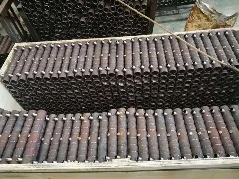
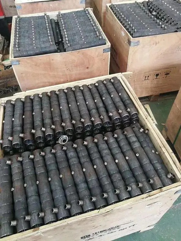
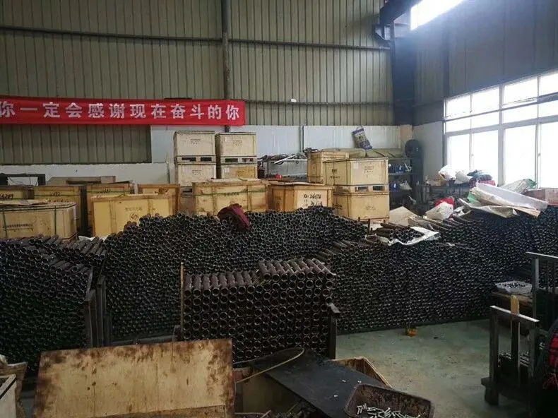
Product Packing and Shipping