Commercial Building Construction Steps and Schedule: Full Process Guide
Commercial Building Construction Steps in this project focus on coordinated execution of steel reinforcement processing, formwork systems, and concrete pouring procedures. The work begins with rebar cutting, bending, straight-thread connection, and on-site inspection to ensure strength and compliance. Formwork construction includes columns, beams, slabs, and shear walls, emphasizing alignment, support stability, and surface quality. Concrete pouring procedures follow strict placement, vibration, curing, and construction joint treatment requirements. Each step ensures structural integrity, safety, and quality control, forming a complete, efficient workflow for commercial building construction.
1、Structural Engineering Overview
This project comprises hotel and commercial components. The hotel includes a guest tower and a banquet hall podium, while the commercial section features a commercial tower and a commercial podium. The total site area is 20,288.5 square meters. The total floor area is 97,906 square meters.
Table 1-1 Structural Overview Table
| Structural Division | Above-ground Floors | Height (m) | Structural Type |
| Hotel Tower | 24 | 99.3 | Frame-Shear Wall |
| Hotel Podium | 4 | 23 | Frame |
| Commercial Tower | 25 | 41 | Frame-Shear Wall |
| Commercial Podium 1 | 1 | 7.5 | Frame |
| Commercial Podium 2 | 2 | 12 | Frame |
The main structure of this project has been largely completed. The remaining work is as follows:
1.1. Hotel Section:
- Hotel Main Building Frame Level 2, Columns 2~R/2 and 2~16/R: Formwork completed, concrete not yet poured;
- Hotel Main Building Frame Level 2, Beams 2~16/F and F~R/16: Formwork completed, concrete not yet poured;
- South Machine Room Roof Parapet Wall: Reinforcement tying and formwork completed, concrete not yet poured;
- The following equipment foundations on the hotel main building roof remain unbuilt: 184kg foundation at Axis 6 left, 4000kg foundation at Axis 9 left, 265kg foundation at Axis 10 right, 130kg and 1500kg foundations at Axis 10 left, and 218kg foundation at Axis 13 left;
- The 184kg equipment foundation at Axis 13 on the north machine room roof remains unbuilt;
- All ventilation shafts on the roof have not yet been constructed.
1.2、Commercial Section:
- Reinforcement tying completed for parapet walls at Y~U/29, 29~32/Y axis of the commercial main building;
- Reinforcement tying completed for parapet walls at C~D/32, 31~32/C axis of the commercial main building;
- All ventilation shafts of the commercial main building remain unbuilt for now.
1.3、Basement Level 1:
- The east wall and lobby walls of Elevator P1 remain unbuilt;
- The shaft walls and lobby walls of Elevators P6, P7, P8, and P9 remain unbuilt;
- The storage room (Class E) on the west side of Fire Compartment 4 retains construction openings: 1.96m x 2.22m and 1.96m x 2.6m;
- North and south walls of the food preparation room in Fire Compartment 4 remain unbuilt;
- Walls of elevator shafts S3 and S4 remain unbuilt;
- A 3720mm-wide opening remains in the smoke exhaust shaft at the weak point equipment room location between axes 28 and 29;
- A 4180mm-wide opening remains at the low-voltage distribution room location between axes 29 and 30;
- Crane access openings remain unsealed;
- Elevator shaft walls at P14, P15, P10, P11, P12, and P13 are unbuilt;
- Post-pour joints remain unsealed;
1.4、Basement Level 2:
- S1 elevator shaft not yet bricked up;
- S2 elevator shaft not yet bricked up;
- North supply air shaft of S1 not yet bricked up;
- The area south of the fire hydrant box southeast of the reserved rainwater treatment equipment room remains unbricked;
- Elevator shafts P6, P7, P8, P9, P10, P11, P14, and P15 remain unbricked;
- The construction joint has not yet been sealed;
- The reserved openings for the tower crane have not yet been sealed;
2、Reinforcement Work
2.1、Overview of Reinforcing Steel Raw Materials
The steel reinforcement used in the podium and tower sections of this project primarily consists of two grades: Grade I steel HPB300 (A8) and Grade III steel HRB400 (C8 to C28).
2.2、Reinforcement connection selection
Mechanical joints shall be used in members specifically designated as axially tensioned or slightly eccentrically tensioned (such as tie rods in trusses and arches, and lower hanging columns), as well as in structural members directly subjected to dynamic loads.
For longitudinal reinforcement with diameter d≥25, frame columns, and frame beams, Grade 3 mechanically connected joints may be used when mechanically connecting longitudinal reinforcement.
The joint position of rebar diameter should be located in areas subject to lower stress, and joints should be staggered. When lap splices are used, within a zone extending 1.3 times the lap length on either side of any splice center, or when mechanical or welded splices are used within a zone extending 35d on either side of any splice center (where d is the larger diameter of the longitudinal reinforcement and 35d is not less than 500mm), the ratio of the cross-sectional area of longitudinal reinforcing bars with lap splices to the total cross-sectional area of all longitudinal reinforcing bars shall comply with the provisions of the following table:
| Joint Type | Tension Zone | Compression Zone |
| Tied Lap Splice | 25% | 50% |
| Mechanical or Welded Joint | 50% | Unlimited |
2.3、steel reinforcement raw materials
- Provide a construction schedule to ensure timely delivery, and conduct thorough counting, inspection, and acceptance of reinforcing steel quantities.
- Strictly verify material certificates, quality certificates, and re-test reports for incoming reinforcing steel.
- Conduct batch re-testing by furnace batch number and diameter in accordance with national standards such as “Hot-Rolled Ribbed Steel Bars for Reinforced Concrete.”
- Particular attention must be paid to structural longitudinal reinforcing bars: The ratio of the measured tensile strength to the measured yield strength shall not be less than 1.25; and the ratio of the measured yield strength to the specified strength standard shall not exceed 1.3. Reinforcing bars shall only be processed and used after all retest performance requirements are met.
- Upon arrival, steel bars shall be stacked separately according to the quantity, type, and specifications required by each processing workshop to facilitate fabrication.
- The stacking area shall be firm and level, with wooden pallets laid to elevate the bars at least 200mm above the ground to prevent rust and contamination. Covering shall be provided during windy or rainy weather for protection.
2.4、Reinforcement Construction Process
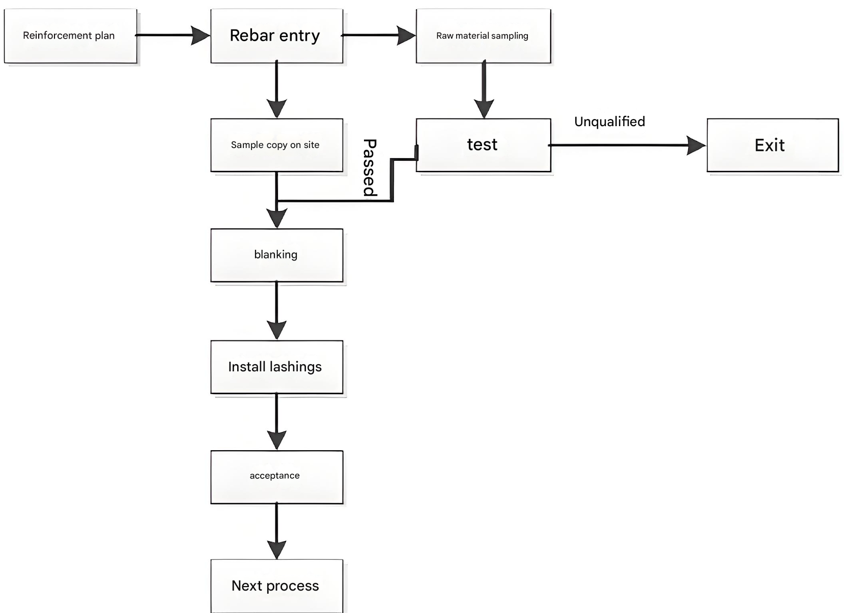
2.5、Reinforcement processing
All steel bars in this project will be processed on-site and lifted to the installation site using tower cranes.
1. Prepare ingredients
Based on the rebar material list, develop the raw material plan in advance. When ordering materials, comprehensively consider the usage of raw materials and formulate the plan with an appropriate ratio of 9m and 12m lengths to minimize processing losses. Rebars must be clean and undamaged prior to processing; oil stains, paint residues, and rust must be thoroughly removed before use.
During construction, if the supplied rebar types and specifications do not conform to the design drawings, substitution should generally not be permitted. When substitution is absolutely necessary, the design intent and properties of the substitute steel must be fully understood, and all code requirements must be strictly adhered to. When replacing the original design’s longitudinal reinforcement with rebar of a higher strength grade, conversion shall be based on the principle of equal tensile load-bearing capacity design values, and the minimum reinforcement ratio requirements must be met. All details of proposed substitutions must be submitted in writing to the owner, designer, and supervisor. Steel replacements may only be implemented after receiving written approval from the design unit.
Before cutting reinforcing bars, strictly verify the raw material reports for the bars. Conduct batch raw material inspections according to local testing requirements. Use only after the re-test reports are approved.
2. Straightening Reinforcing Bars
HPB300 grade reinforcing bars shall be straightened using a rebar straightening machine. For HRB400 grade reinforcing bars, the supplier shall ensure that the bars remain free from bending or deformation during transportation. Should bending or deformation occur, the bars shall be straightened by hammering or bending.
3.Rust removal of steel bars
Before processing reinforcing bars, remove rust caused by moisture or rainwater. All bars shall be manually descaled using wire brushes. Bars with severe rusting that has formed old rust or flaky rust shall not be used.
4.Fabrication of Reinforcing Bars
4.1、Reinforcement Schedule
Based on the construction drawings and specifications, detailed reinforcement arrangements shall be prepared for all project sections. During this process, if excessive reinforcement density is identified at frame joints, hidden columns, or beam-column connections, layout verification must be conducted first to implement preemptive measures facilitating on-site fabrication. Reinforcement schedules must undergo review, verification, and approval before proceeding with steel fabrication.
Cutting Principles: Steel bars of the same specification should be grouped by length, combining long and short lengths for coordinated material allocation. Cut longer lengths first, followed by shorter lengths, to minimize short ends and reduce waste.
4.2、Cutting Reinforcing Bars
Use rebar cutters and angle grinders to cut the rebar. When cutting, ensure the distance between the blade and the impact blade’s cutting edge. For rebar with a diameter <20mm, overlap by 1-2mm; for rebar with a diameter ≥20mm, leave approximately 3mm to ensure the required cutting length.
When cutting reinforcing bars, verify the material list to ensure the specified dimensions match the actual formed dimensions. Only proceed with mass cutting and forming after confirming accuracy.
4.3、Forming of steel bars
Bend the cut steel bars into sections, segments, layers, parts, and specifications according to the reinforcement plan. The key points of steel bar forming processing control are the processing of stirrups, ladder bars, spacing frames, horse stools, and the processing quality of straight threaded joints.
HPB300 grade steel bars shall be formed manually using a ratchet wrench, with the ends formed into 180° hooks. The arc bending radius shall be 1.5 times the steel bar diameter and shall not be less than the radius of the main bar, with a straight length of 10d. The ends of negative moment reinforcement bars at the slab support shall be formed into 90° hooks, with the straight length meeting design requirements. HRB400 grade steel bars shall be bent using a steel bar bending machine. When the bar ends are formed into 135° bends, the arc bending radius shall be 2.5 times the bar diameter and shall not be less than the radius of the main bar. The straight length shall comply with design requirements. For seismic structures, the straight length of stirrups shall be 10d.
To ensure the accuracy of stirrup fabrication, angle steel must be welded onto the operating platform of the fabrication equipment to form 135°, 90°, and hook straightness control lines.
4.4、Rolling Straight Thread Sleeve Machining
4.4.1、Manufacturing of rebar coupler
Reinforcing bar connection sleeves shall be manufactured in accordance with the product design drawings. Critical dimensions—outer diameter, length, thread profile, and precision—shall undergo production inspection.
Dimensions of reinforcing bar connection sleeves shall meet product design requirements.
Reinforcing bar connection sleeves shall be free from surface cracks, internal threads, and severe rust.
Prior to packaging, sleeves shall be fitted with protective end caps. Foreign objects must not enter the sleeve interior.
4.4.2、Straight Thread Machining
Reinforcing bars shall not be cut using hot-working methods; instead, a toothed cutting machine shall be used. The ends of the bars should be flat and perpendicular to the bar axis, free from horseshoe-shaped deformations or twists. Bar ends must not be bent; any bending shall be straightened, as shown in the figure below.
Clamp both ends of the rebar onto the threading machine for threading. During threading, use a water-soluble cutting coolant for cooling and lubrication. For large-diameter rebar, cut to the specified dimensions in multiple passes to ensure thread accuracy. Inspect using go gauges and no-go gauges; inspection tools are shown in Figure.
After threading rebar ends, the quality of each threaded connection must be inspected individually by the operator using a go gauge or no-go gauge. The thread profile must match the thread gauge, and the cut end diameter must fall within the permissible tolerance range of the go gauge or no-go gauge. Non-conforming threaded ends must be cut off and reprocessed.
After processing and passing inspection, threaded ends of reinforcing bars shall be immediately fitted with protective caps or threaded coupling sleeves to prevent damage during handling. The surface of threaded ends shall be free from severe rust or damage.
4.4.3、On-site Inspection of Reinforcing Bar Joint Connections
Sampling Method for On-site Inspection of Threaded Rebar Ends:
Each processed threaded rebar end shall undergo self-inspection. Non-compliant ends shall be cut off and reprocessed. Self-inspected compliant ends shall be randomly sampled for inspection by the on-site quality inspector. A single work shift’s processed ends shall constitute one inspection batch, with 10% randomly sampled. The pass rate of the sampled rebar threads shall not be less than 95%. If the pass rate falls below 95%, the sampling rate shall be doubled. Should the pass rate still remain below 95%, all rebar threads shall undergo individual inspection, and only those passing inspection may be used.
Operators must undergo technical procedure training and obtain certification upon passing the assessment before commencing work.
The thread profile and pitch of machined threaded ends must match those of the connecting sleeve. The cumulative length of stripped threads within the effective threaded section shall be less than half the circumference of one thread pitch.
5.Reinforcing Bar Connection
5.1、Straight thread connection
The advantages of straight thread sleeve connections for reinforcing bars include: high connection strength, rapid on-site construction speed, reduced labor intensity for workers, and the ability to prefabricate straight thread connections off-site for on-site jointing. Four joint types are available: standard, dual-thread, reducer, and adjustable, all utilizing sleeves for connection. For this project, standard connections are used for most reinforcing bars. Reverse thread connections are employed at construction joints and post-pour strips, while reducer connections are used for bars of differing diameters.
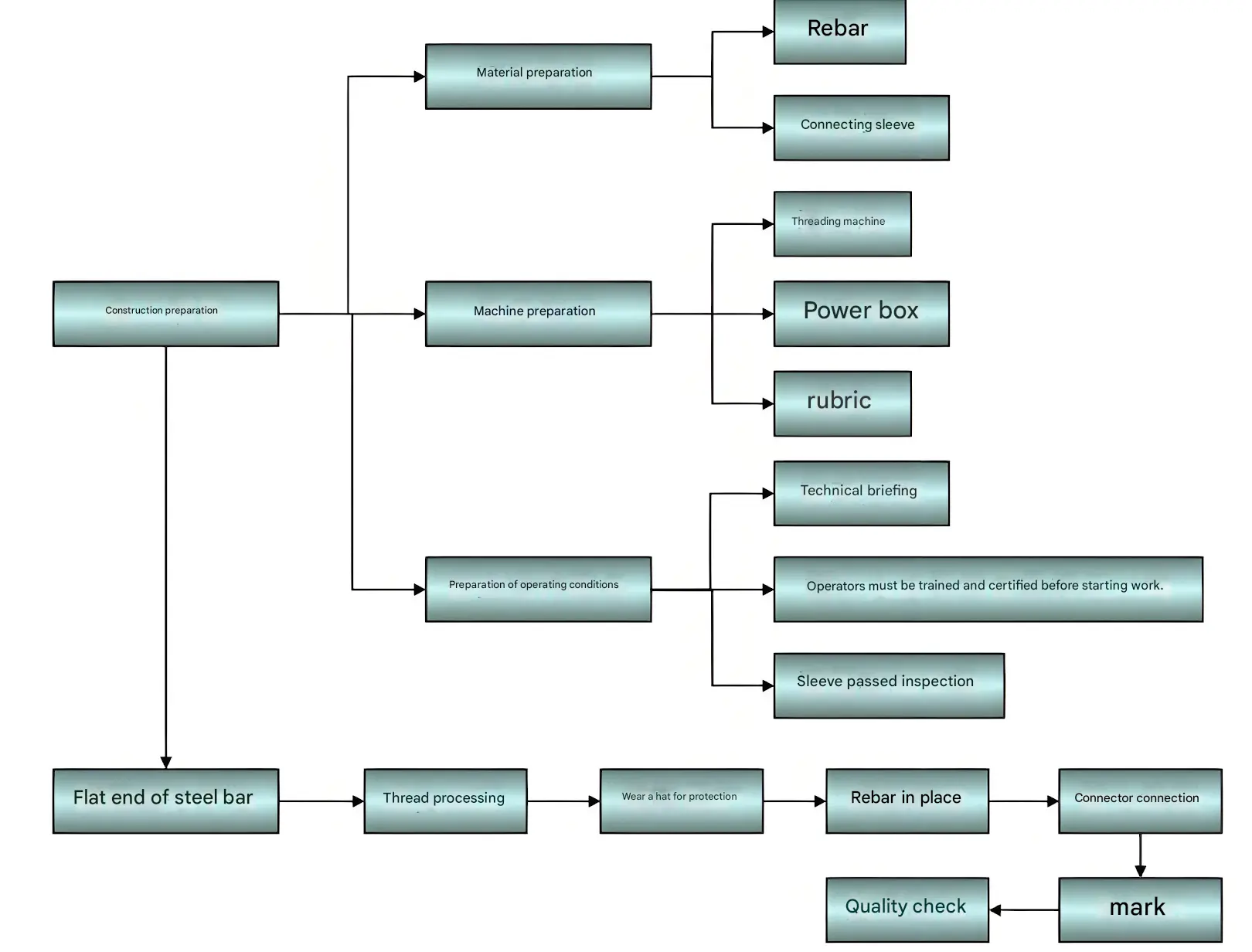
5.1.1、Construction Preparation
Determine the locations and quantities of reinforcing bars requiring straight thread connections according to the design drawings, and provide training for the operators.
The connecting sleeve shall be made of high-quality carbon structural steel or other steel materials determined to meet requirements through type testing.
Primary tools and equipment, such as the straight threading machine for reinforcing bars, limit stop blocks, thread ring gauges, torque wrenches, standard wrenches, and angle grinders, shall be prepared. Refer to Figure 5.5.1-1 for details on positioning and inspection of straight-threaded reinforcing bars.
5.1.2、Operating conditions
Operators have undergone training and assessment and are certified to perform their duties.
When testing the fit between rebar and steel sleeves, any rebar exhibiting horseshoe bends, burrs, kinks, or excessively large longitudinal ribs must first be straightened or ground down using a hand-held grinder. Cutting off excess sections with electric welding is strictly prohibited.
5.1.3、Key Construction Points
- When connecting steel bars of different diameters, the diameter difference should not exceed two grades in a single connection.
- When connecting steel bars, use a pipe wrench to tighten the threads, ensuring both threaded ends are centered and tightly pressed against each other within the coupling sleeve. Alternatively, secure with a locknut and mark the connection. After joint assembly, no more than one and a half complete threads should be exposed at either end of the sleeve. Refer to Figure 6.2.2-6 for a detailed diagram of straight thread connections.
- Before connecting, remove the plastic protective cap from the upper end of the lower rebar to expose the threads. Clean any contaminants such as cement paste from the threads. When connecting the bars, align them along the axis and screw them into the coupling sleeve. Screw the upper bar with the pre-threaded sleeve onto the bar to be connected. Use a torque wrench to tighten the joint to the specified torque value until the wrench clicks at the preset torque. Mark the joint with paint to prevent missed tightening.
- Refer to Figure 5.2-1 for connection examples. Torque wrenches must be calibrated every six months. The torque wrench is shown in Figure 5.2-2.
5.1.4、Joint Inspection
5.1.4.1、Visual inspection:
Operators shall meticulously inspect the appearance quality of each joint individually. First, ensure that the specifications of the rebar and sleeve match. Exposed threads shall not exceed one and a half complete threads. Quality inspectors shall use torque wrenches to conduct random checks on joint tightness.
5.1.4.2、Visual inspection:
Prior to commencement of rebar connection operations and throughout construction, each batch of incoming rebar shall undergo joint connection process inspection. Such inspections shall comply with the following requirements:
For each rebar specification, no fewer than three joint specimens shall be tested. The parent material of the joint specimens shall undergo tensile strength testing.
The tensile strength of all three joint specimens shall not be less than 0.95 times the actual tensile strength of the connected rebars.
On-site inspections shall include visual quality checks and uniaxial tensile tests.
On-site inspection of straight thread joints shall be conducted per acceptance batch. Joints of the same grade, type, and specification using identical materials under identical construction conditions shall be inspected and accepted in batches of 500 units. Batches with fewer than 500 units shall also constitute a single acceptance batch.
Each acceptance batch shall be inspected and accepted based on the performance requirements for Grade I joints. Three specimens shall be randomly selected from the engineering structure for tensile strength testing: if the tensile strength of all three specimens meets or exceeds the standard value for the corresponding grade of reinforcing steel, the acceptance batch shall be deemed qualified. If any specimen fails to meet the tensile strength requirement, six additional specimens shall be retested. Should one specimen still fail to meet the requirement during retesting, the acceptance batch shall be deemed non-compliant. For straight threaded joints, the failure mode in unidirectional tensile testing—whether due to rupture of the steel bar base material, rupture of the sleeve, or slippage of the steel bar from the sleeve—shall be considered acceptable provided the strength requirement is met.
When ten consecutive acceptance batches pass the unidirectional tensile test with all samples meeting requirements, the number of joints per acceptance batch may be increased to 1,000. Randomly inspect 10% of joints of the same specification for visual quality. Reinforcing bars and sleeves must match specifications, and no complete threads shall be exposed at the joints.
Use a torque wrench to conduct spot checks on the construction quality of joints. The sampling quantity is as follows: For columns and shear wall embedded columns, 15% of the total joints shall be sampled, with no fewer than one joint sampled per component. For walls, every 100 joints shall constitute one acceptance batch, with three joints sampled per batch. All sampled joints must pass inspection. If any single joint fails, the entire acceptance batch shall undergo individual inspection, and any nonconforming joints identified shall be reinforced.
5.1.4.3、Quality Records:
Certificate of Quality or Test Report for Reinforcing Bars upon Delivery; Mechanical Properties Test Report for Reinforcing Bars; Certificate of Conformity for Steel Sleeves; Type Test Report for Joint Specimens.
5.2、Tied Lap Splice
The lap joints and lap lengths of reinforcing bars must comply with design and code requirements.
- The clear horizontal spacing between reinforcing bars at lap splices shall be greater than or equal to the bar diameter and not less than 25 mm.
- Bottom reinforcement bars in cast-in-place reinforced concrete slabs shall not be spliced at the midspan. Top reinforcement bars shall not be spliced at supports.
- Extension of bottom longitudinal reinforcement bars in beams shall be located at supports or within one-third of the span on either side of supports. Extension shall not occur at the midspan. Extension of top longitudinal reinforcement bars shall be within one-third of the span at the midspan. Extension shall not occur at supports.
5.2.1 Reinforcing steel tying
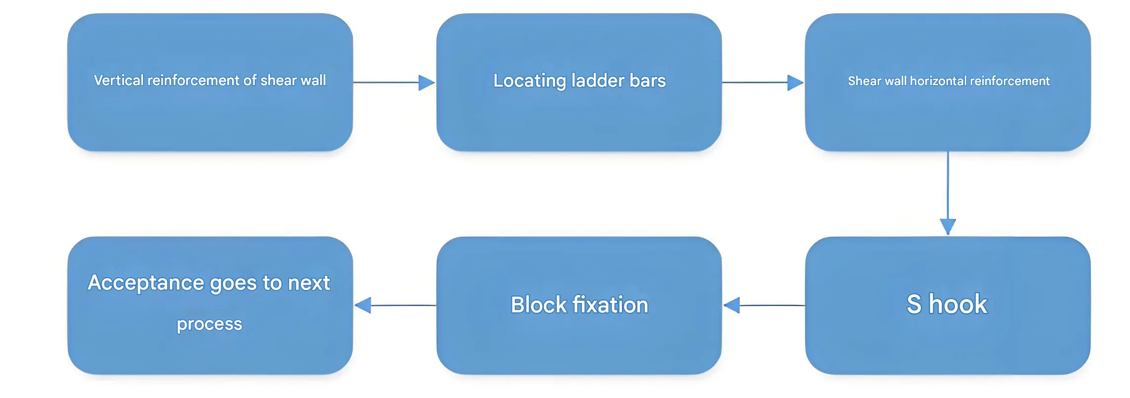
5.2.1.1 Process Flow
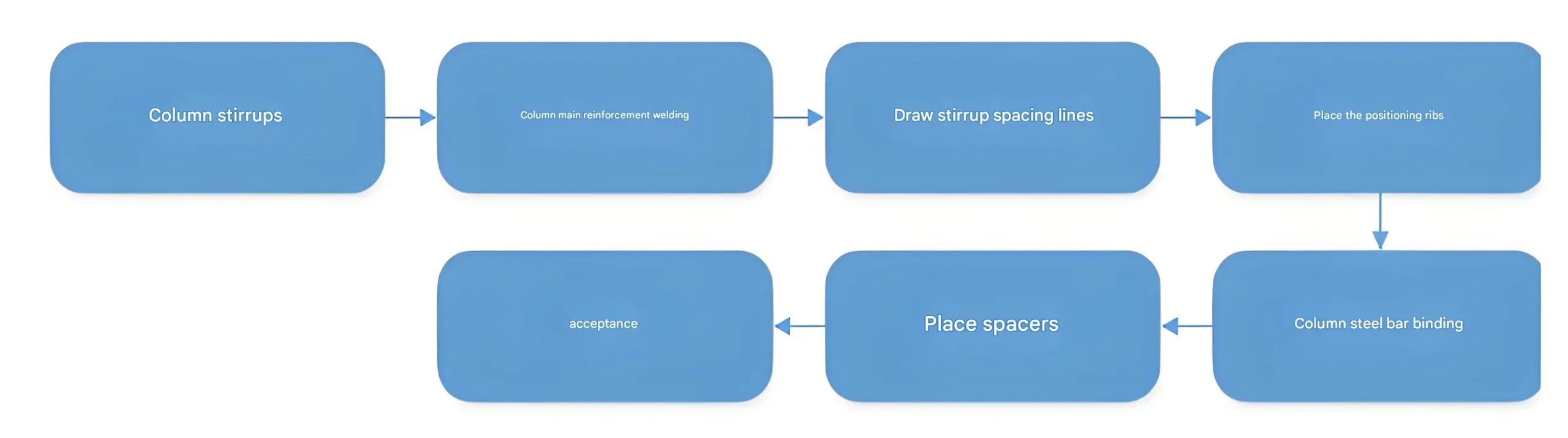
5.2.1.2 Key Points for Binding
1、Trim and clean up:Clean concrete debris from the reserved column reinforcement bars below. Align the vertical reinforcement position according to the column edge line (for the lowest column, fix the vertical reinforcement position based on the column edge line; re-align and secure during formwork installation).
2、 Install stirrups onto the column bars according to their form and quantity, ensuring the stirrup openings are arranged to wrap around the four corners of the column.
3、Vertical Reinforcement Connection Location:Vertical steel bar straight thread joints in columns shall not be placed within the stirrup reinforcement densification zone. Vertical steel bar joints in the same plane shall be staggered by 50% with a minimum offset of 35d (where d is the column main bar diameter) and no less than 500.
4、Perform a visual inspection of the vertical rebar connections or conduct sampling tests as required. After passing inspection, temporarily secure the vertical alignment with scaffolding and begin tying the stirrups.
5、Column Reinforcement Binding:
① Column stirrup configuration: Square columns shall use closed stirrups and composite stirrups with hooks. Seismic stirrup hooks shall have a 135° bend angle with a straight leg length of no less than 10d.
② Spacing of Staggered Stirrups: Mark stirrup spacing with chalk on the diagonal reinforcement of the column, starting 50mm from the concrete surface, with a spacing of 200mm. When staggered placement aligns with straight threaded sleeves, employ upper and lower densification to avoid placing stirrups on the sleeves.
③ When tying column main bars to stirrups: Use loop ties at corners and figure-eight ties in the middle. Excess tying wire must face inward toward the component.
④ Inspect columns for skew or distortion. After adjustment, install a column positioning frame at the top of the column (to fix rebar positions, reusable) and place 1–2 column limiting stirrups at the top. Securely tie the positioning frame and limiting stirrups to the column main rebars. See Figure 6.2.2-10 for the positioning frame.
⑤ After completing column reinforcement tying, install protective layer spacers. For the 25mm protective layer of column main bars, use plastic spacers clipped onto the main bars at 600mm intervals in a staggered pattern.
5.2.2 Wall Reinforcement Binding
5.2.2.1 Process Flow
5.2.2.2 Key Points for Binding
1、Before tying wall reinforcement, clean contaminated steel bars with a wire brush. Surveyors promptly mark the inner and outer edges and control lines on the wall. Concrete workers use a flat chisel to chip away along the marked lines and thoroughly remove loose mortar and stone debris.
2、Adjust the position of the swing arm
Based on the marked inner and outer wall lines, correct reinforcing bars with excessive or insufficient protective layers by bending them at a 1:6 ratio. Also correct bars with spacing deviations exceeding ±5mm.
When aligning the vertical reinforcement bars for the formwork, the first vertical bar must be positioned 50mm from the edges of both side columns. Intermediate bars should be arranged from the center outward toward both sides according to the design drawings. When reaching the second vertical bar, if the spacing does not meet the drawing requirements, adjustments are permitted; however, the bar spacing must not exceed the design specifications.
3、Wall reinforcement tying
When tying horizontal wall reinforcement bars, position the horizontal distribution bars according to the spacing of vertical ladder bars. (Before tying, first level the ladder bars using string lines and temporarily secure them with upper, middle, and lower horizontal bars. The vertical ladder bars should be one grade larger than the wall vertical bars and serve as substitutes for them. with 2–3 ladder bars per wall section). The first horizontal distribution bar must be positioned no more than 50mm from the concrete surface and above the first hidden column stirrup. All intersections between vertical wall bars and horizontal bars must be secured with binding wire using figure-eight knots.
5.2.3 Reinforcing Steel Binding
5.2.3.1 Process Flow
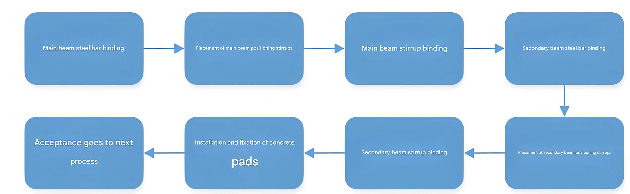
5.2.3.2 Key Points for Binding
- Chalk Line Marking, Formwork installation and handover completed. Clear debris from formwork surfaces. Use iron red chalk to mark grid lines for longitudinal and transverse reinforcement spacing on formwork panels. The starting reinforcement for slabs shall be positioned 50mm from beam edges and wall edges.
- Determining Placement Order: Unless otherwise specified, for bottom reinforcement mesh, place short-span reinforcement first, followed by long-span reinforcement. For top reinforcement mesh, place long-span reinforcement first, followed by short-span reinforcement.
- Joint Locations: Upper reinforcement shall be placed within the middle third of the span. Lower reinforcement shall be placed within the support third of the span. Joints shall be staggered within 1.3 times the lap length as per code requirements.
- Anchoring Requirements at Slab Edges: For end-supported beams, the anchorage length of the slab’s tension reinforcement is: – For the lower layer: Not less than the greater value between 1/2 beam (wall) width and 15d. – For the upper layer: La. The anchorage bend of the lower layer reinforcement faces upward, while that of the upper layer reinforcement faces downward.
- All intersection points of the steel mesh shall be tied securely. Adjacent tie points shall form a figure-eight knot. Overlap sections shall be tied with three knots. All tie wire ends shall face inward toward the concrete.
- For the lower layer of the slab steel mesh, protective layer spacers shall be placed during tying. Plastic spacers shall be used, spaced at 600mm intervals in a staggered pattern.
- Support the upper and lower reinforcement layers with I-shaped stirrups. Fabricate the stirrups from C14mm rebar at 1200mm intervals. Refer to Figure 6.2.2-16 for the stirrup configuration.
- To ensure negative moment reinforcement ends align in a straight line, continuous white thread must be threaded through the ends for positioning and binding when tying negative moment reinforcement in load-bearing sections.
- When openings are reserved in floor slabs, for openings less than 300mm, slab reinforcement may be looped around the opening edges. For openings greater than 300mm, slab reinforcement must be cut and repositioned according to drawing specifications.
3、Formwork System
3.1、Pillar

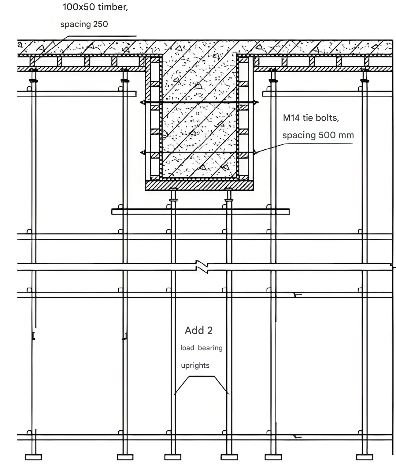
Column formwork utilizes 15mm thick film-faced plywood, with 100×50 timber battens serving as vertical ribs and Φ48.3×3.0 steel pipes as horizontal cross-ribs encircling the formwork. As shown below:
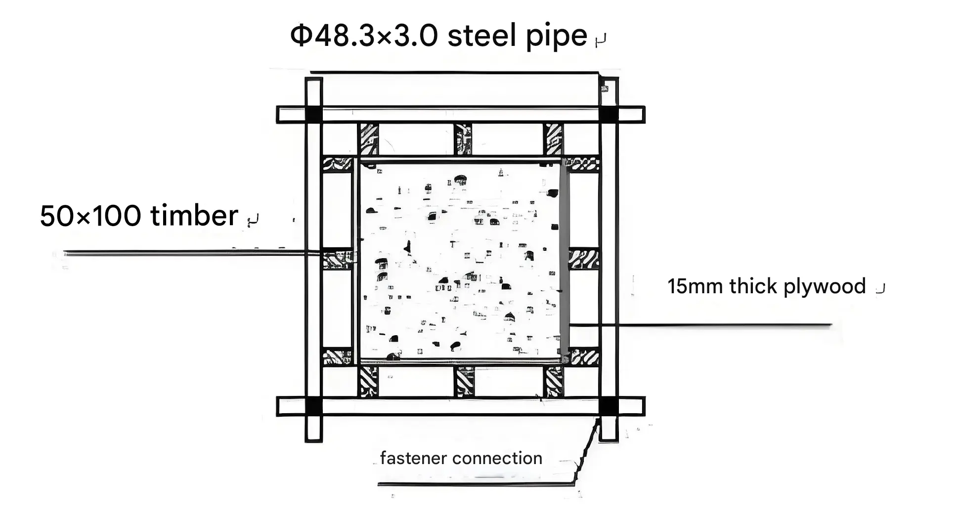
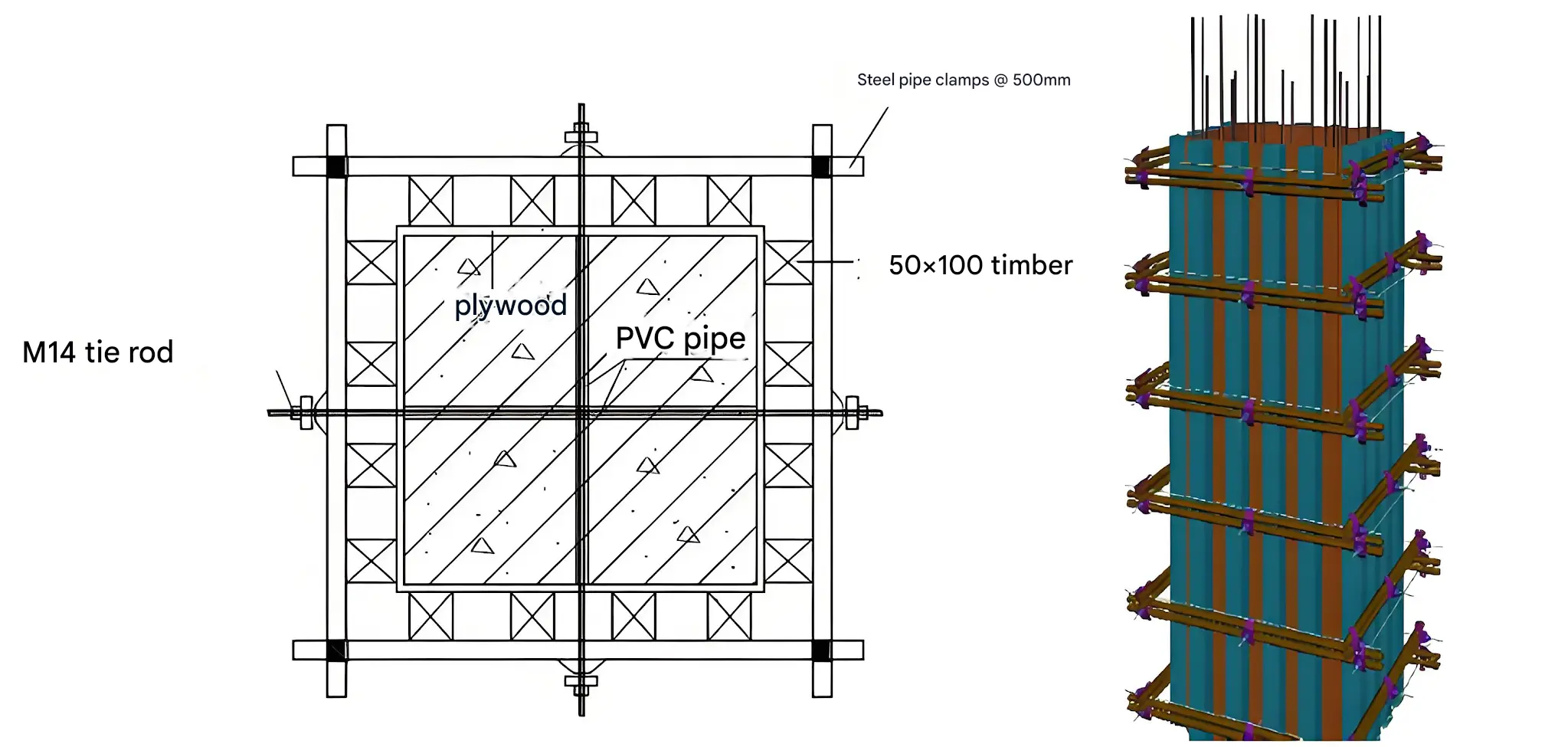
Column formwork employs 15mm thick plywood panels with vertical ribs made of 50×100mm timber battens spaced at 200mm intervals. Column ties utilize double steel pipes with specifications φ48.3×3.0mm, installed at 500mm intervals.
When the side length of a column exceeds 600mm, an additional M14 tie rod must be installed at the center of that side. See the figure below.
3.2、Floor slab, Beam
3.2.1 floor slab
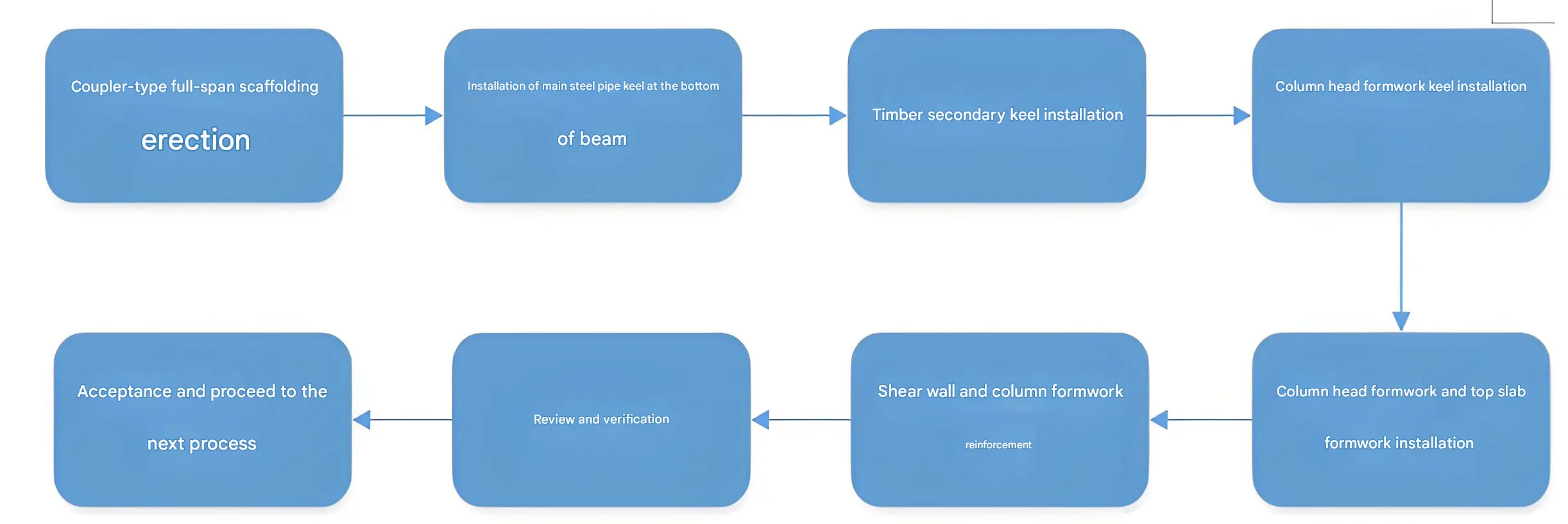
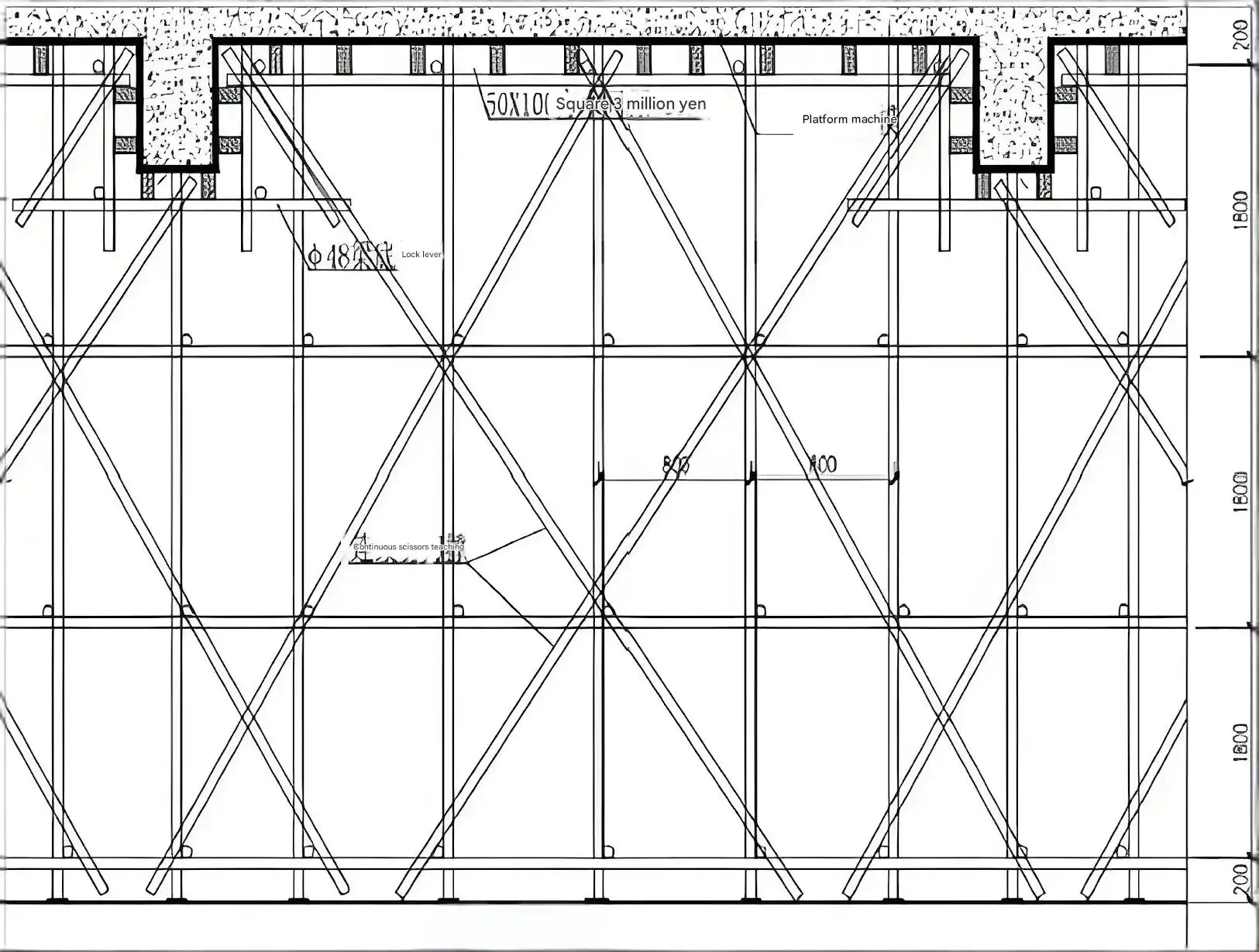
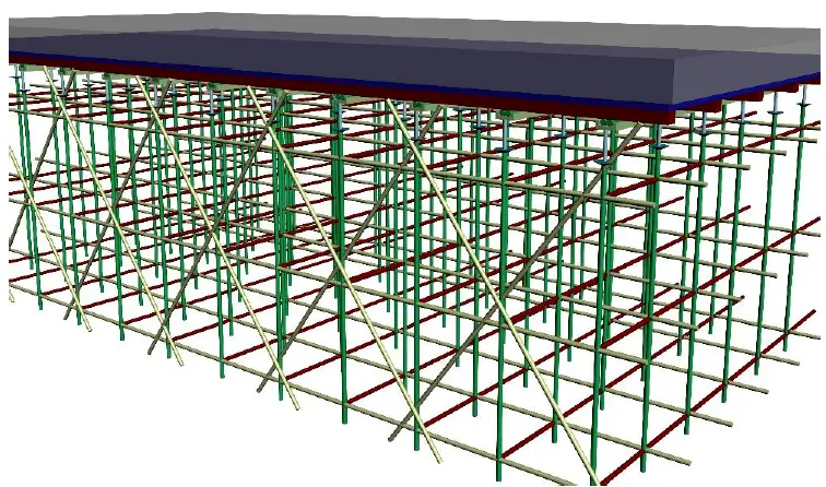
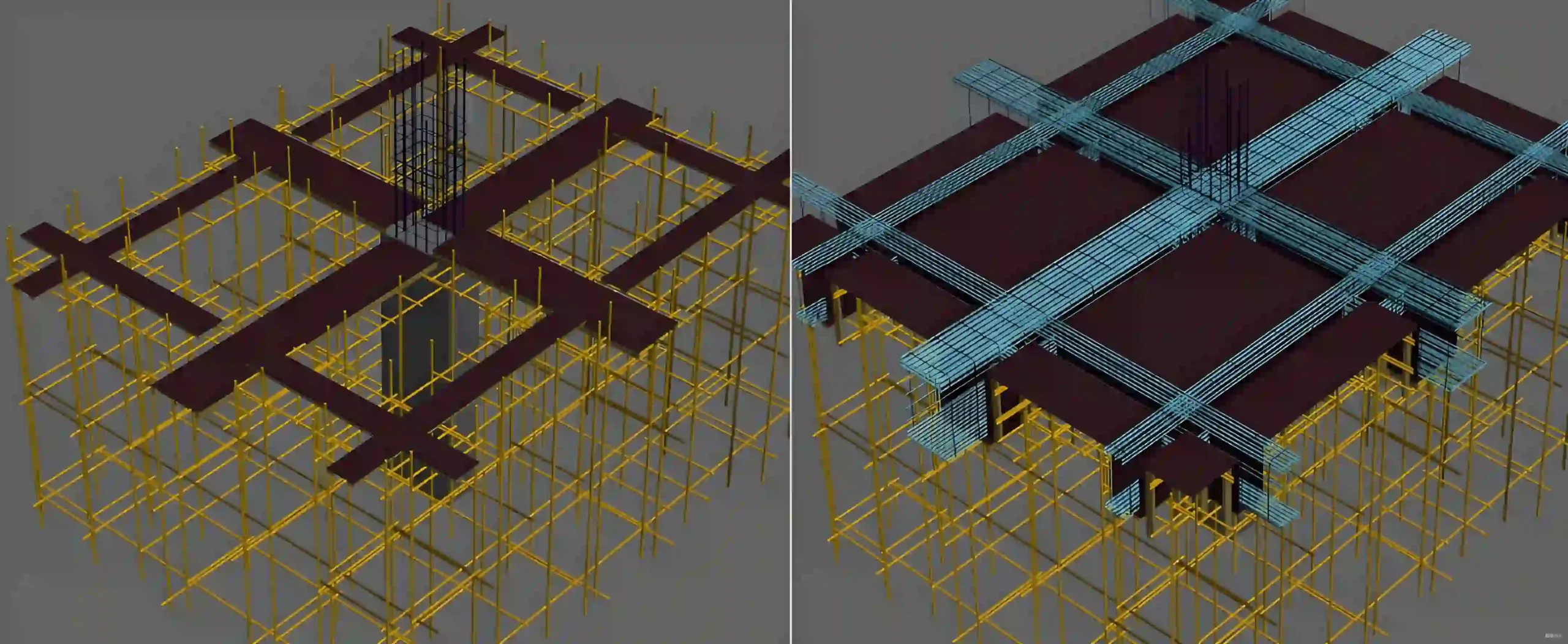
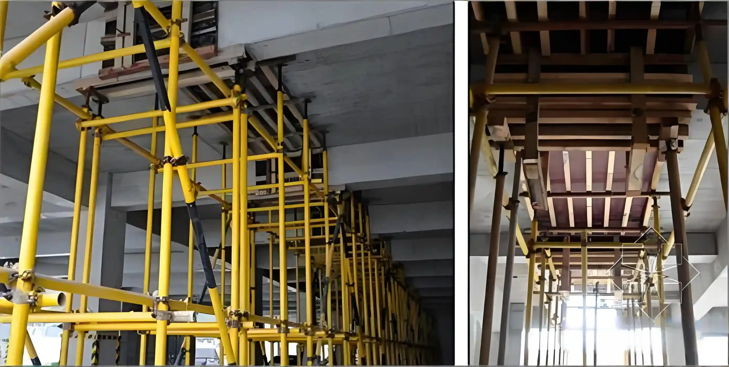
Supports utilize coupler-type steel tube scaffolding with longitudinal and transverse spacings of 800–900 mm (adjusted based on thickness and height), and a step distance of 1800 mm. The bottom sweep rod connects to the upright poles via couplers, positioned 200 mm above ground level, while the top cap rod remains no more than 300 mm from the formwork base. After erecting the full-span scaffolding, install φ48 steel pipe main girders and 50mm × 100mm secondary girders according to the slab bottom elevation. Secondary girders shall be spaced no more than 300mm apart. Then lay the beam bottom formwork.
3.2.2 Beam
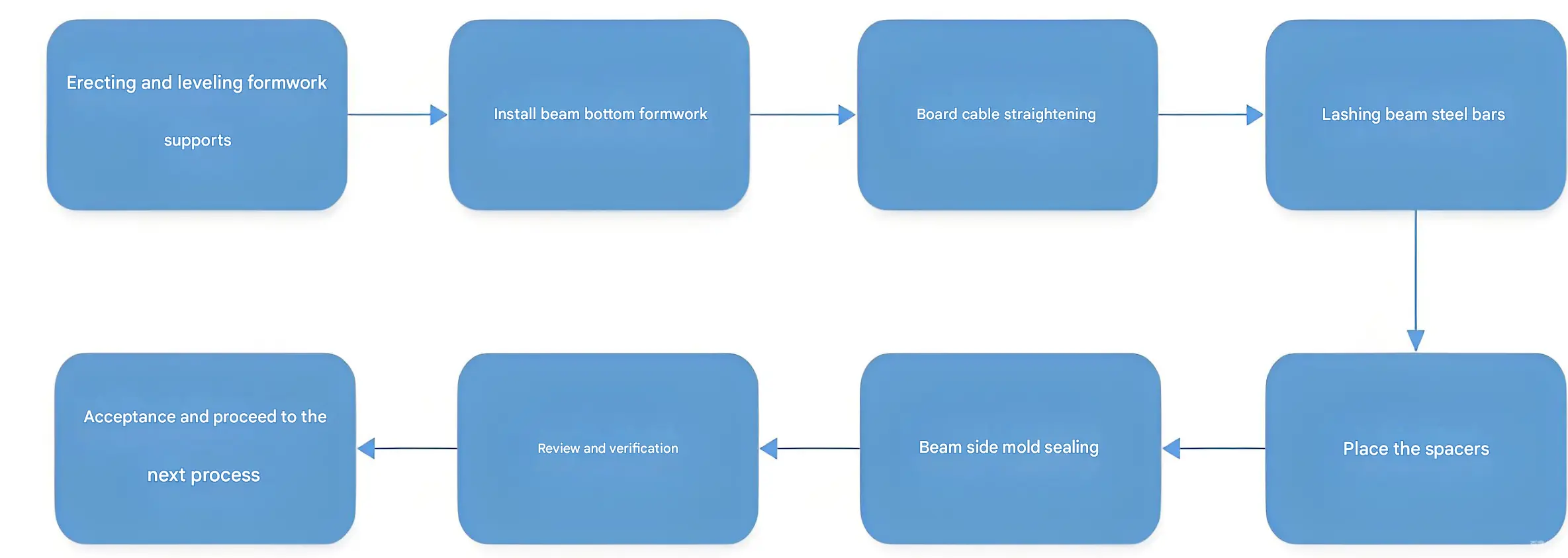
Beam formwork is assembled using 15mm thick plywood panels, with 50×100mm timber battens configured as beam side and bottom formwork. Beam supports utilize coupler-type steel pipes. Secondary backing battens for side formwork are arranged along the beam longitudinal direction at 400mm intervals. When beam height is ≤600mm, side formwork may omit tie rods, relying solely on horizontal steel pipe props supporting the formwork panels. For beams exceeding 600mm in height, the side formwork is secured with M14 tie rods. The vertical spacing of tie rods shall not exceed 500mm, and the horizontal spacing shall not exceed 750mm. See the diagram below for details.
3.3 Construction Joint
When installing the bottom formwork for beams and slabs on the same floor level, quick-release support systems shall be installed on both sides of the floor slab post-pour joint formwork (which may be retained during overall formwork removal). This ensures that after removing the bottom formwork for beams and slabs, the supports remain in place and continue functioning properly, preventing the formation of cantilevered structures. The formwork support system shall be identical to that used for the floor slab.
4、Concrete Work
The remaining concrete volume for this project is relatively small, so we have opted to use a combination of tower cranes and construction elevators for concrete transportation during pouring.
4.1 Concrete Batching Plant Selection
We evaluated the qualifications of ready-mix concrete suppliers, their capacity to meet project requirements, and concrete transportation distances. After comprehensive consideration, we ultimately selected two local batching plants as the ready-mix concrete suppliers for this project.
4.2 Concrete Placement Methods
4.2.1 Wall, Column, Beam, and Slab Pouring
- Before concrete pouring, clear debris from the formwork and complete concealed work inspections for reinforcing bars, pre-embedded pipes and conduits, and construction joints.
- Before pouring concrete for walls and columns, lay a 20-30mm thick bed of cement mortar matching the concrete mix ratio at the base. Starting from the corners, evenly tamp the mortar into the formwork using a shovel. Do not pour directly into the formwork using buckets or pump pipes to prevent mortar from splashing onto the formwork and hardening. Gently vibrate the mortar adhering to the reinforcement bars with a vibrator to dislodge it. Avoid laying the mortar too early or too widely to prevent cold joints between the mortar and concrete. Pour concrete immediately after laying the mortar. For shear walls, maintain a distance of approximately 3m between the mortar placement point and the concrete pouring point.
- During wall and column concrete placement, use a straightedge to control layer thickness (illuminate formwork interiors with lamps during nighttime operations). Perform layered placement and compaction, strictly limiting each concrete layer to approximately 800mm thickness. Free-fall discharge height must not exceed 2m. Before discharge, require mixer trucks to rotate at high speed for 1 minute to prevent concrete segregation.
- Consult the meteorological station prior to concrete pouring to avoid construction during rainy weather.
- The treatment method for beam-column joints and connections between shear walls and slabs is detailed in the figure below. This separation technique also applies to interfaces between concrete of different grades, such as columns and beams (slabs), shear walls and beams (slabs), etc. During separation, wire mesh must be secured to the pre-fabricated reinforcement frame, which is then spot-welded at the required separation points. Construction joints are established at the interfaces between columns and beams (slabs), and between shear walls and beams (slabs) where concrete of different strength grades meet. To ensure joint construction quality, construction joints are positioned 2h (where h is the beam height) from the beam (wall) edge, using wire mesh as side formwork.
- The freshly poured concrete sections of beams and slabs should be promptly finished and compacted to ensure a smooth and dense surface.
4.2.2 Pouring the Construction Joint
4.2.2.1 clean and prepare all construction joints
- Workers shall thoroughly remove loose or settled concrete within the construction joint using small tools such as hammers and steel chisels. Disturbing or damaging reinforcing bars is strictly prohibited.
- Particular attention shall be given to removing all temporary supports within the construction joint, including reinforcing bars, wire mesh, formwork, and timber battens.
- Install expansion waterstop strips at the post-pour joints of foundation slabs and exterior walls.
- Remove debris, especially slurry residue and silt. Flush with a water gun connected to an air compressor while simultaneously suctioning with a slurry pump until thoroughly clean.
4.2.2.2 Adjusting reinforcing bars:
- Adjust the type, grade, specification, quantity, spacing, position, and protective layer of reinforcing bars according to the corresponding design drawings;
- At the base slab where reinforcing bars must be cut to clear debris from the post-pour strip, perform bar welding with tie bars as per code requirements and reinforce with additional bars of the same specification;
- Remove rust from corroded reinforcement bars using wire brushes or rust removers. Perform rust removal on deformed or corroded waterstop plates at shear wall construction joints;
- After reinforcement adjustments, conduct self-inspection and handover procedures. Proceed with subsequent construction only after passing inspection by the supervising engineer.
4.2.3 Concrete pouring
- Concrete pouring should generally proceed from lower to higher elevations. For special components requiring unique pouring sequences, ensure concrete does not flow erratically within the pouring area, prevent mixing of different grades of concrete in separate sections, and maintain pouring conditions for other areas as well as subsequent pours.
- Continuously pour the base slab first. Before initial setting occurs at the wall interface, pour the wall’s construction joint to eliminate any construction joints between slab and wall.
- Use concrete one grade higher than adjacent sections and ≥C30. Add 12% SY-T composite fiber crack-resistant admixture.
4.3 Concrete Curing
Cured concrete should be immediately covered with plastic sheeting for insulation, topped with a layer of cotton felt for additional warmth. Delay the removal of concrete side forms; once removed, immediately wrap them with plastic sheeting and cotton felt. The curing period must not be less than 14 days (for waterproofing requirements). Watering frequency should ensure the concrete remains moist. Pedestrian traffic and installation of formwork/scaffolding are permitted only after the concrete strength reaches 1.2 MPa. During curing, if inadequate maintenance causes surface whitening or fine shrinkage cracks, intensify curing measures by thoroughly watering and extending the curing period.
4.4 Finished Product Protection
- When removing formwork, do not use sledgehammers to forcefully strike or pry with crowbars, to avoid damaging the concrete surface.
- Personnel may only access the poured concrete after its strength reaches 1.2 MPa.
- When covering the concrete surface, operate while standing on scaffolding boards and avoid leaving footprints.
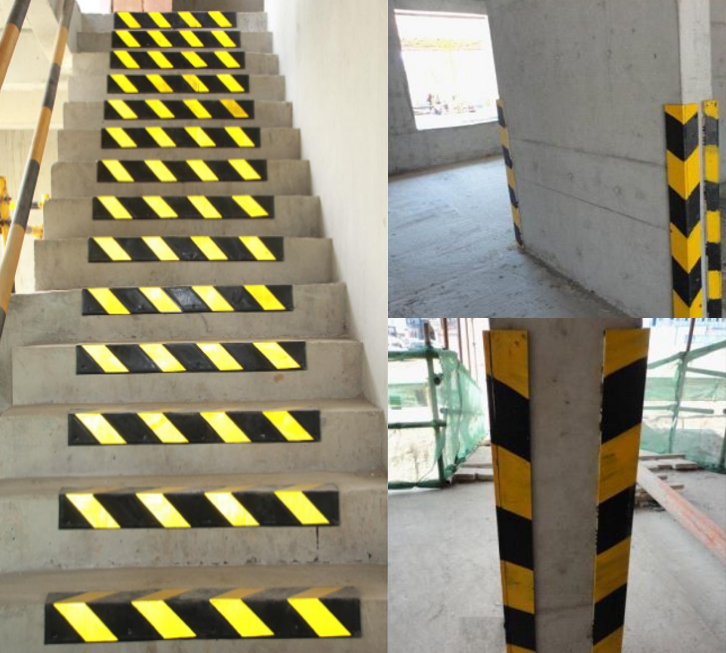
- After column formwork removal, protect the column’s positive corners using scrap formwork strips. See illustration below.