half grout sleeve coupler
Description
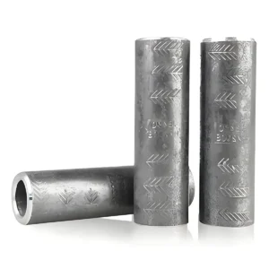
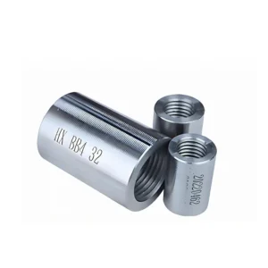
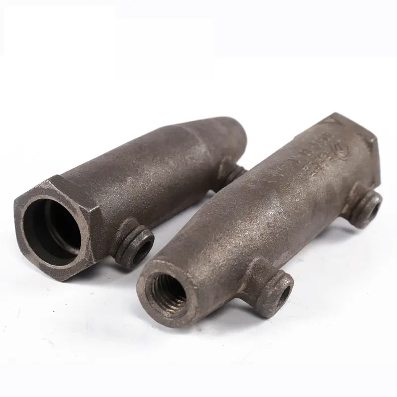
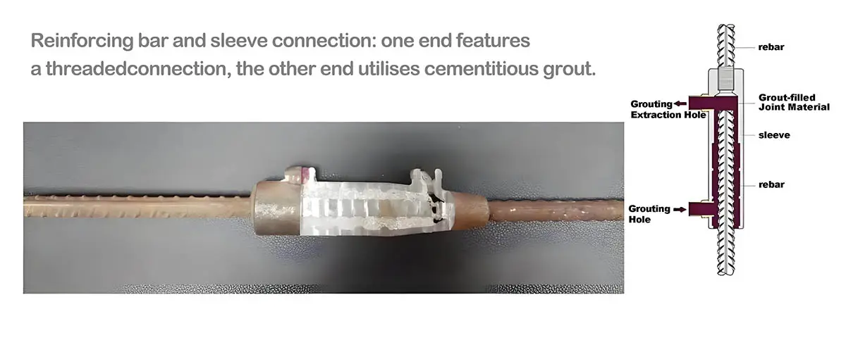
half grout sleeve coupler is a type of steel reinforcement sleeve., comprising a specially machined sleeve, complementary grouting material, and reinforcing bars as a composite assembly. During the reinforcement connection process, rapid-setting, non-shrink grout is injected to achieve bonding and interlocking between the reinforcement and sleeve. This joint type offers reliable performance, broad applicability, and straightforward installation.
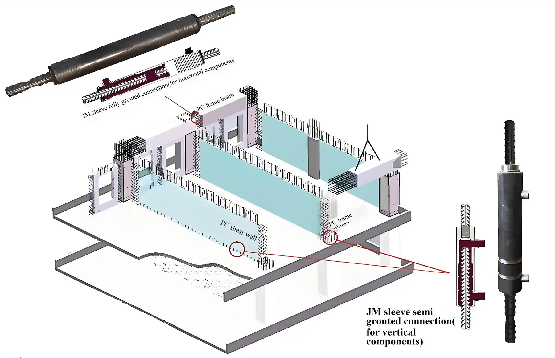
Grout sleeve coupler are categorised into two types: half grout sleeve coupler and full-grout sleeve coupler. This sleeve connection technology is applicable in reinforced concrete structures, steel structures, bridge engineering, offshore oil drilling platforms, and offshore wind turbine towers.
Features of half grout sleeve coupler
- Fifty per cent of connections can be completed via threading at the factory, facilitating both quality control and the secure installation of sleeves within moulds, thereby maximising the advantages of prefabrication;
- Compared to full-sleeve grouting connections, this reduces the number of stirrups required in densely reinforced zones;
- Compared to full grouting, it substantially reduces grout consumption. When connecting reinforcing bars of the same grade, the grout height can be halved, significantly lowering grouting pressure and compartmentalisation difficulties while ensuring superior grout quality. Furthermore, should grout deficiency occur, the semi-grouted connection at the bar ends minimises impact on load transfer, whereas full grouting at the bar’s highest stress point markedly compromises connection integrity;
- The superior material quality and high machining precision of half-grouting sleeves enable maximum increase in double-row reinforcement H-values within shear wall structures, provided the required concrete cover thickness is maintained.
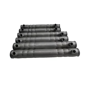
Parameter of half grout sleeve coupler
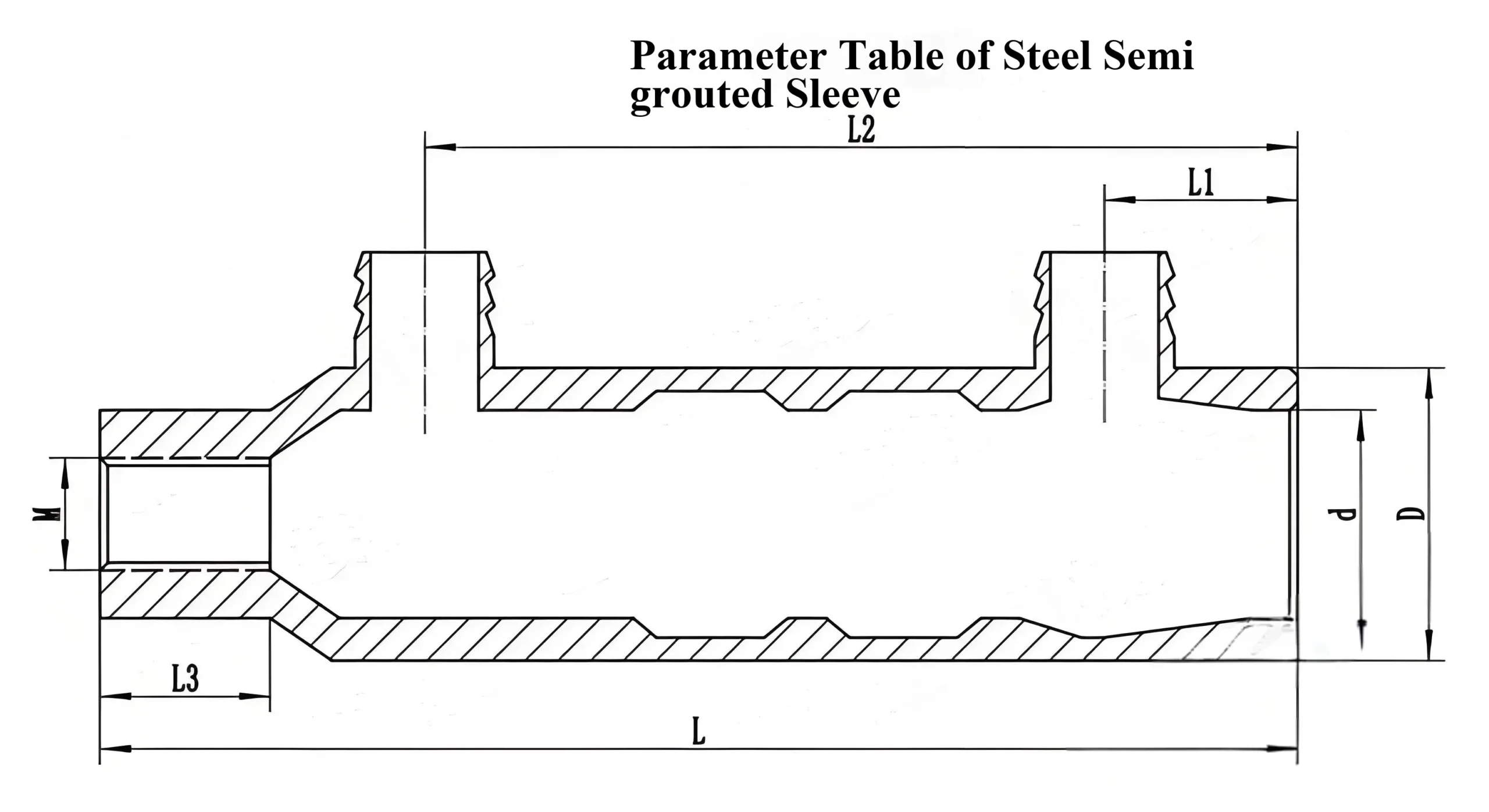
| Model | Rebar Connection Diameter | Thread Diameter (M) | Thread Angle | D | d | L | L1 | L2 | L3 | Minimum Rebar Insertion Length | Maximum Rebar Insertion Length | Net Weight (kg) |
| GTJB4 12/12 | 12 | M12.6*2.0 | 60° | 35 | 24.3 | 137 | 25 | 97 | 20 | 96 | 106 | 0.5 |
| GTJB4 14/14 | 14 | M14.6*2.0 | 60° | 38 | 27.3 | 155 | 25 | 113 | 22 | 112 | 122 | 0.6 |
| GTJB4 16/16 | 16 | M16.6*2.0 | 60° | 40 | 29.3 | 175 | 25 | 131 | 24 | 128 | 138 | 0.75 |
| GTJB4 18/18 | 18 | M18.6*2.5 | 60° | 42 | 31.3 | 195 | 25 | 147 | 26 | 144 | 154 | 0.8 |
| GTJB4 20/20 | 20 | M20.6*2.5 | 60° | 45 | 33.3 | 210 | 30 | 162 | 28 | 160 | 170 | 1 |
| GTJB4 22/22 | 22 | M22.6*2.5 | 60° | 50 | 36.3 | 230 | 30 | 179 | 31 | 176 | 186 | 1.5 |
| GTJB4 25/25 | 25 | M25.6*2.5 | 60° | 54 | 39.3 | 267 | 30 | 214 | 33 | 212 | 222 | 2.05 |
| GTJB4 28/28 | 28 | M28.6*3.0 | 60° | 63 | 45.3 | 313 | 35 | 257 | 36 | 252 | 262 | 2.6 |
| GTJB4 32/32 | 32 | M32.6*3.0 | 60° | 71 | 51.3 | 355 | 35 | 293 | 42 | 288 | 298 | 4.1 |
Precautions During Product Installation
- During the processing of threaded rebar ends, strict control must be exercised to ensure the ends remain straight. Simultaneously, the overall length of the rebar must be carefully managed, taking into account the length required for the overlapping connection with the sleeve thread. After formwork removal, the deviation of the exposed rebar shall be within 0 to +10mm;
- Thread diameter of rebar threads shall be verified using a thread ring gauge: the pass-end thread gauge must screw in smoothly, while the stop-end thread gauge must not be screwed in beyond three times the thread pitch;
- Use a torque wrench to securely connect approved threaded rebar ends to grouting sleeves. Both exposed thread length and tightening torque must meet specifications.
- Secure sleeves to formwork using dedicated fasteners to ensure precise positioning and prevent grout leakage.
- Grouting pipes and drainage pipes must be securely installed. Where necessary, tie-down fasteners may be used to prevent detachment or grout leakage during concrete pouring;
- Prior to component dispatch, re-inspect the grouting sleeve position, anchor rebar length, sleeve interior cavity, and grouting/drainage piping to ensure compliance with requirements.
Precautions During Grouting Operations
- During grout preparation, first pour water into the mixing bucket, then add approximately 70% of the grout material. Mix using a dedicated mixer for 1–2 minutes before adding the remaining grout material. Continue mixing for a further 3–4 minutes until the grout is thoroughly and uniformly blended. Allow to stand for approximately 2–3 minutes to permit air bubbles within the mixture to dissipate naturally before use.
- When ambient temperature exceeds the grout’s upper usage limit (35°C), conduct an actual workability test to ensure grouting is completed within the material’s usable timeframe.
- Crucially, grouting must be finished within 45 minutes of initiating mixing with water, allowing sufficient contingency time for unforeseen construction issues.
- After the grout has set, remove the specialised rubber plugs from the grouting holes and drainage holes, ensuring the solidified grout surface within the holes remains at least 5mm above the lower edge of the drainage holes;
- Subsequent construction may only commence after the compressive strength of grout test specimens cured under identical conditions reaches 35 MPa. Typically: – At ambient temperatures above 15°C, components must remain undisturbed for 24 hours; – At ambient temperatures between 5°C and 15°C, components must remain undisturbed for 48 hours; – At ambient temperatures below 5°C, thermal insulation measures must be implemented.
Product Grout Saturation Inspection
During actual construction works, the degree of grout saturation is the most critical factor in ensuring construction quality. Therefore, after the grout has set, all grouted joints must undergo saturation checks. Since sleeves are cast within the components during prefabrication, verifying grout saturation has long posed a challenge in construction acceptance procedures.
The conventional method involves removing the sealing plug from the grout discharge hole to verify whether the upper surface of the solidified grout within the hole extends at least 5mm above the lower edge of the hole opening. Alternatively, grout saturation can be determined by measuring the resistance between embedded conductors. This entails drilling symmetrical holes near the grout discharge port on the grout sleeve, then embedding measuring wires within the gap between the sleeve’s inner wall and the reinforcing steel, as illustrated below.
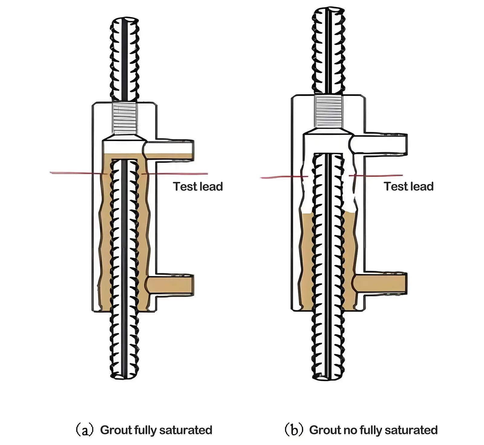
As grout primarily conducts electricity via ionic pathways, its resistance is substantially higher than that of the reinforcement or sleeve. Inadequate grouting will yield an infinitely high resistance measurement between the embedded wires. Conversely, when grouting is complete, the measured resistance will approximate the intrinsic resistance of the grout material itself.
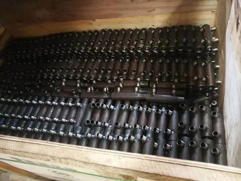
Product Packing and Shipping